Week 10: Machine Design
Outline:
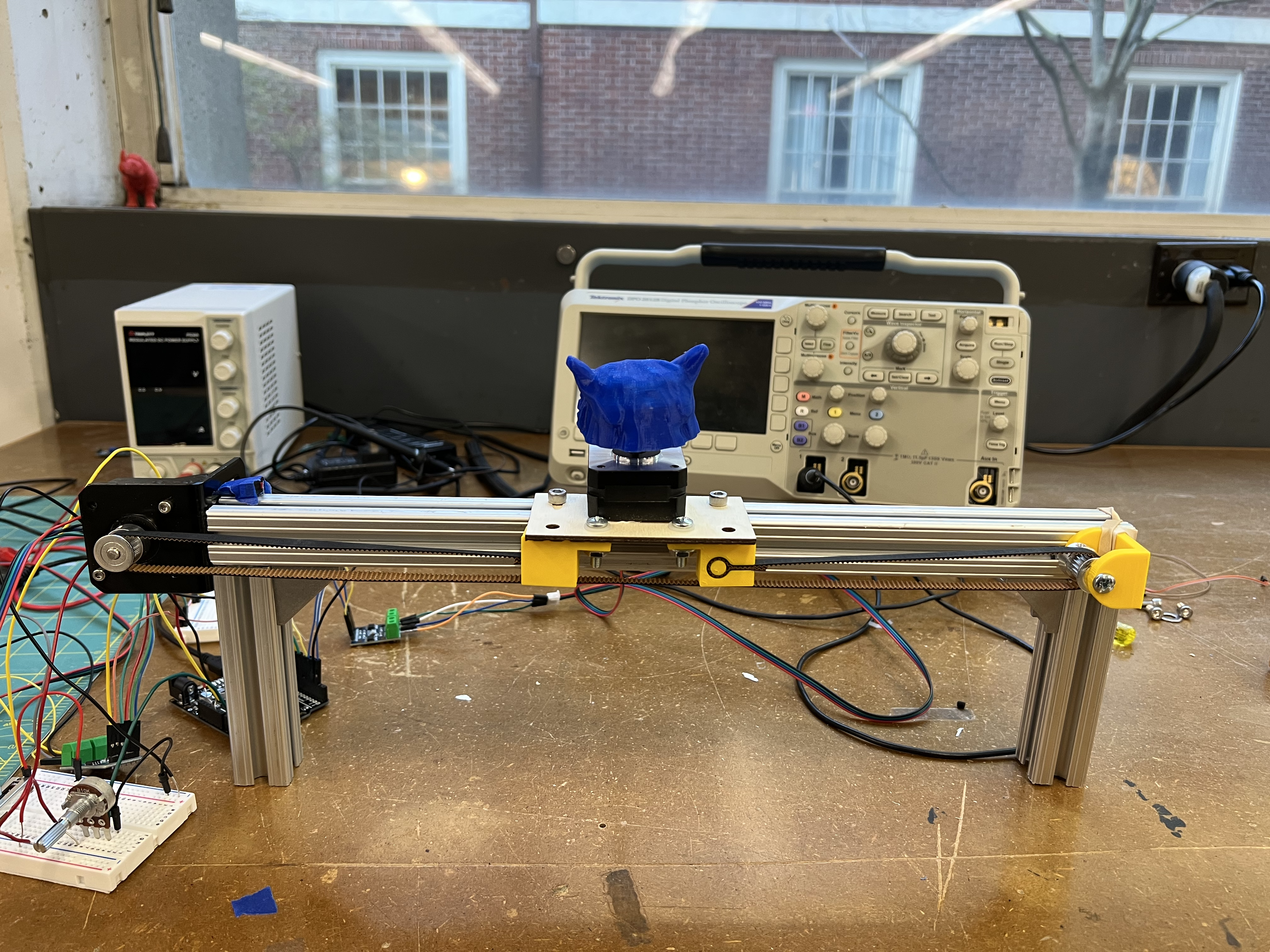
This week, Joseph and I worked together to expand on the previous week's Owl Head on Cup idea. Our goal was to make a 2-axis machine, each axis controlled by a single stepper motor. This worked! One axis uses linear motion to move the head from side to side, while the other uses rotational motion to spin the owl head.
Controlling Two Motors:
To even beginning building the 2-axis machine, we needed to get comfortable with stepper motors. Luckily, there are 2 great Arduino libraries that are pre-built for this: Stepper and AccelStepper. Stepper is more suited to simple stepwise movements, while AccelStepper can run the motor at varying acceleration and velocities. While the AccelStepper documentation is a bit confusing to traverse, there are several great examples included with the library that really make sense of the library's power. In our case, where we wanted slow, controlled movements of the machine, Stepper was a more natural, barebones choice.
Each motor was controlled with a Dual L9110 H-Bridge motor driver to ramp up voltage as necessary. A single motor requires 4 pins to specify its control. This circuitry setup is demonstrated in the image below.
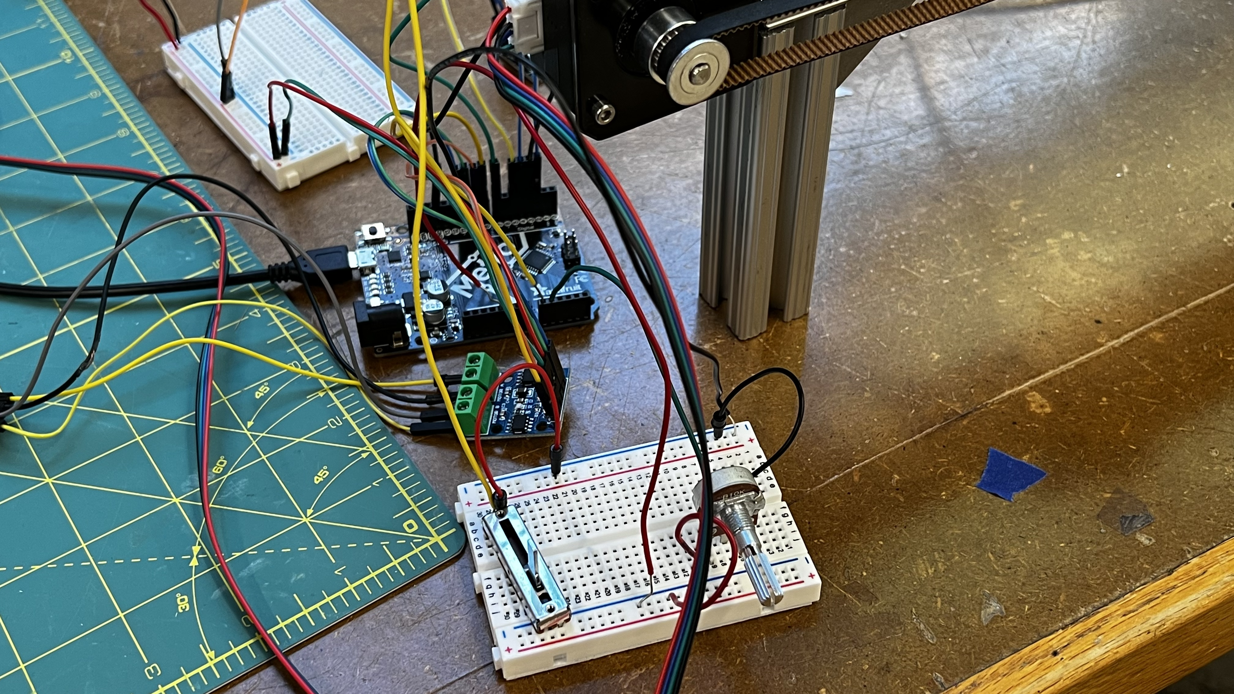
The position of the linear axis motor was controlled by a slide potentiometer. In the initialization of the machine, the linear axis motor brings the central platform all the way to the edge of the rail, until it triggers a limit switch. The platform then moves slightly away from the very edge, and position is set to 0. Future movements are then controlled by a slide potentiometer which maps directly onto the physical space of the rail. Effectively, the limits of the slide potentiometer are hard coded to match the limits of the rail after the zeroing initialization step.
As for the second, rotational axis, this is controlled with a standard rotary potentiometer, where the distance from the center of the potentiometer's range corresponds to the speed in the corresponding direction. Thus, if the potentiometer is rotated counterclockwise from its centerpoint, the owl head too will rotate counterclockwise. Both this and the linear axis control is implemented in the code below.
#include <Stepper.h>
#include <AccelStepper.h>

int potX = A0;
int potValX = 0;
int posGoalX = 0;
int currentPosX = 0;
int stepSize = 5;
bool triggered = false;

int limitPin = 7;
int limit = 1;

int in = A1;
int potValR = 0;
int spdR = 0;

const int stepsPerRevolution = 200;
Stepper sX(stepsPerRevolution, 8, 9, 10, 11);
Stepper sR(stepsPerRevolution, 2, 3, 4, 5);

void setup() {
  // put your setup code here, to run once:
  Serial.begin(9600);

  pinMode(limitPin, INPUT_PULLUP);

  while (!triggered) {
    sX.step(-1);
    // Serial.println("Step.");

    limit = digitalRead(limitPin);
    Serial.println(limit);
    if (limit == 0) {
      Serial.println("TRIGGERED!");
      triggered = true;
    }
  }
  sX.step(20);
}

void loop() {
  potValR = analogRead(in);
  spdR = map(potValR, 0, 1023, -5, 5);
  sR.step(spdR);

  // put your main code here, to run repeatedly:
  potValX = analogRead(A0);
  Serial.print("Pot: ");

  posGoalX = map(potValX, 0, 1023, 0, 1150);

  Serial.println(posGoalX);
  Serial.println(currentPosX);

  if (currentPosX < posGoalX) {
    currentPosX++;
    sX.step(stepSize);

  }
  if (currentPosX > posGoalX) {
    currentPosX--;
    sX.step(-stepSize);
  }
}
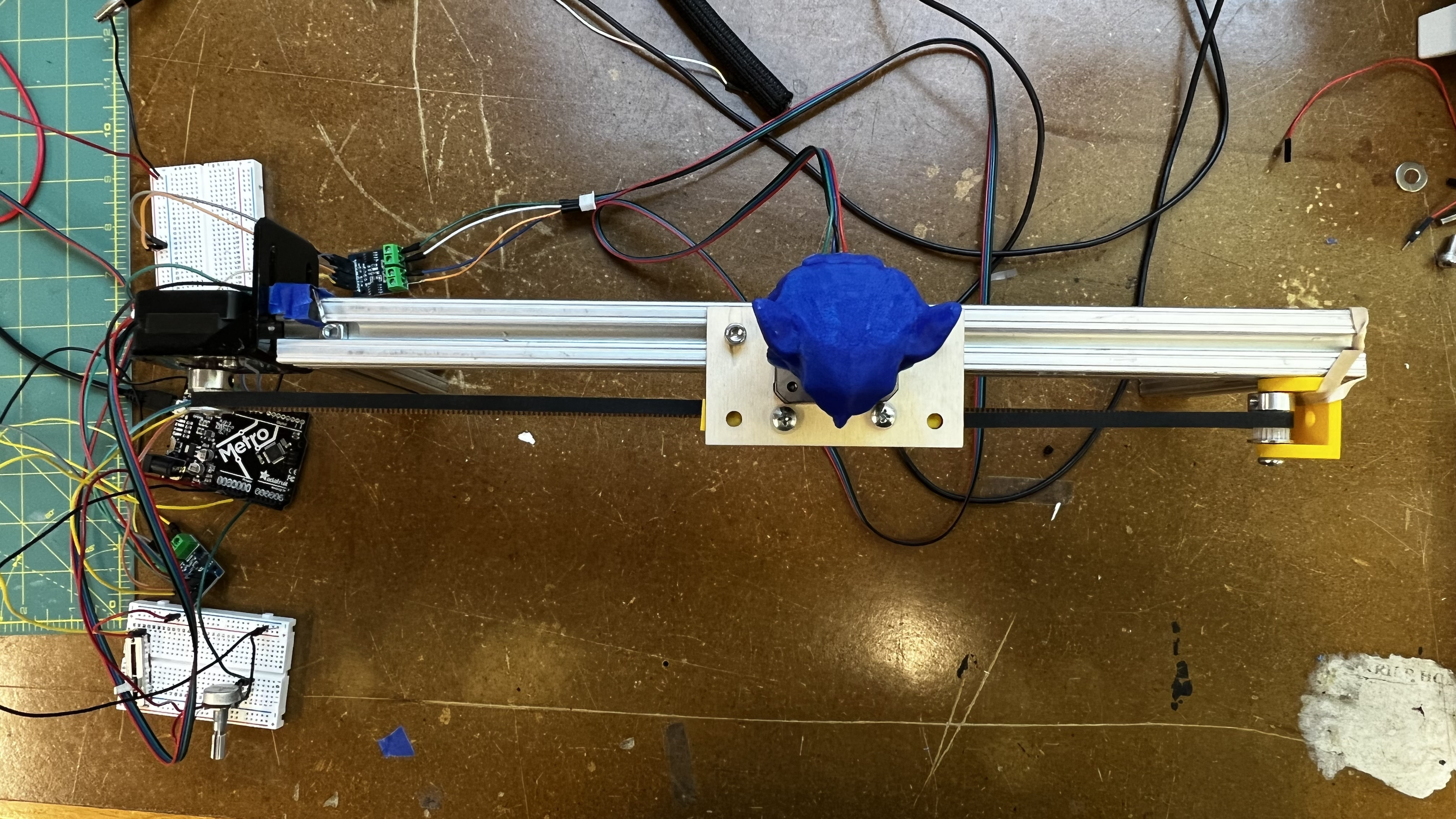
Machine Design:
Joseph was responsible for actually fabricating most of the machine. He assembled the frame from metal bars around the lab, and screwed on the stepper motors with brackets. After laser cutting a platform for the rotational stepper motor with the owl head, he screwed down the motor into this platform for movement along the bar. So much credit to Andrei for his 3D models for a pulley (printed in yellow). Wouldn't have been possible without him! With that being said, here's the final product: