Week 9: Internet of Things and Wireless Communication
Outline:
We designed an owl. Our ideation process went through several stages, landing at an owl with a camera hooked up to it. The output is both the motor rotating and the image produced through the camera. The input will come through a website connected to a Google Firebase app, with which the MCU communicates. Information given by the user through the website goes through a Firebase Realtime Database, where it is regularly accessed by the MCU to determine its behavior (namely, motor speed and direction).
Connecting a Motor to Firebase Database:
My first step was hooking up the ESP32, an MCU with built-in wireless connection capabilities, to a Firebase database. To do that, I followed 2 tutorials: one by Nathan and the other by Rui Santos (RandomNerd). It wasn't too hard to figure everything out, and I thought I'd present a simple list here:
Create a Firebase Realtime Database to Write and Read Data:
- Navigate to the Google Firebase homepage and select Get started.
- Create a project by clicking Add project and giving it a name.
- Select Realtime Database from the menu on the left, click Create database. Do this in Test Mode, which is less secure, but makes connecting to the MCU easier.
- Record the database URL.
- Select the Gear icon in the top right of the left panel. Select Project settings → Service accounts → Database secrets. Hover over the secret key, select Show, copy the key, and record it. This will be used to allow the MCU access to the variables stored in the Realtime Database.
- Select Project Overview from the top left of the left panel to navigate to the project homepage. Under the title Get started by adding Firebase to your app, select the Web icon (</>).
- Ignore the majority of text that appears under Step 2. Add Firebase SDK. Just copy and store all the variables contained within
const firebaseConfig. - Set up a webpage using the following code. Replace the values in the
firebaseConfigvariable with your own Firebase app details. This code creates a String variable in the Firebase database calledLED_STATUSwhich can be toggled either ON or OFF. This offers a simple example of how interacting with a webpage through JavaScript elements can communicate information to the Realtime Database. - Download the library Firebase ESP32 Client by Mobizt.
- Then, upload the following code for controlling an LED to your MCU, credit to Nathan Melenbrink.
- Hook up your circuit, power up the MCU, and control the LED from your webpage!
* At this point, an MCU can be connected to the Realtime Database. However, we would have to edit data directly through the database. Thus, we will create a Firebase app, where we can interact with the database (read/write) through a more user-friendly webpage. *
<!doctype html>
<html class="no-js" lang="en">
<head>
	<meta charset="utf-8" />
	<meta name="viewport" content="width=device-width, initial-scale=1.0" />
	<title>PHYSCI 70: Introduction to Digital Fabrication</title>
</head>

<body>

	 <button id="turn-on" name="turnon">Turn On</button>
	 <button id="turn-off" name="turnoff">Turn Off</button>

	<!-- The core Firebase JS SDK is always required and must be listed first -->
	<script src="https://www.gstatic.com/firebasejs/7.13.2/firebase-app.js"></script>

	<!-- TODO: Add SDKs for Firebase products that you want to use
	     https://firebase.google.com/docs/web/setup#available-libraries -->
	<script src="https://www.gstatic.com/firebasejs/7.13.2/firebase-database.js"></script>

	<script>
	// Your web app's Firebase configuration
	var firebaseConfig = {
		apiKey: "REPLACE_WITH_YOUR_OWN",
		authDomain: "REPLACE_WITH_YOUR_OWN",
		databaseURL: "REPLACE_WITH_YOUR_OWN",
		projectId: "REPLACE_WITH_YOUR_OWN",
		storageBucket: "REPLACE_WITH_YOUR_OWN",
		messagingSenderId: "REPLACE_WITH_YOUR_OWN",
		appId: "REPLACE_WITH_YOUR_OWN"
	};
		// Initialize Firebase
	firebase.initializeApp(firebaseConfig);

	// Get a database reference to our blog
	var ref = firebase.database().ref("/");

	// make the buttons call the function below
	document.getElementById('turn-on').addEventListener('click', turnOn, false);
	document.getElementById('turn-off').addEventListener('click', turnOff, false);

	function turnOn(){
		console.log("turning on");
		ref.update({
			"LED_STATUS": "ON"
		});
	}

	function turnOff(){
		console.log("turning off");
		ref.update({
			"LED_STATUS": "OFF"
		});
	}
</script>

</body>
#include <WiFi.h>                                 // esp32 library
#include <FirebaseESP32.h>                        // firebase library

#define FIREBASE_HOST "esp32-led-9a0ab.firebaseio.com"  // the project name address from firebase id
#define FIREBASE_AUTH ""                    			// the secret key generated from firebase
#define WIFI_SSID ""                            		// input your home or public wifi name
#define WIFI_PASSWORD ""                        		// password of wifi ssid

String fireString = "";                                          // led status received from firebase
int ledpin = 5;

//Define FirebaseESP32 data object
FirebaseData firebaseData;

void setup() {
  Serial.begin(115200);
  delay(1000);
  pinMode(ledpin, OUTPUT);
  WiFi.begin(WIFI_SSID, WIFI_PASSWORD);                          // try to connect with wifi

  Serial.print("Connecting to ");
  Serial.print(WIFI_SSID);
  while (WiFi.status() != WL_CONNECTED) {
	Serial.print(".");
	delay(500);
  }

  Serial.println();
  Serial.print("Connected to ");
  Serial.println(WIFI_SSID);
  Serial.print("IP Address is : ");
  Serial.println(WiFi.localIP());                                // print local IP address
  Firebase.begin(FIREBASE_HOST, FIREBASE_AUTH);                  // connect to firebase
  Firebase.reconnectWiFi(true);
  Firebase.set(firebaseData, "/LED_STATUS", "OFF");              // set initial string of "OFF"
}

void loop() {

  Firebase.get(firebaseData, "/LED_STATUS");                     // get led status input from firebase
  fireString = firebaseData.stringData();                        // change to e.g. intData() or boolData()
  Serial.println(fireString);

  if (fireString == "ON") {                    // compare the input of led status received from firebase
	Serial.println("Led Turned ON");
	digitalWrite(ledpin, HIGH);                // make output led ON
  }

  else if (fireString == "OFF") {              // compare the input of led status received from firebase
	Serial.println("Led Turned OFF");
	digitalWrite(ledpin, LOW);                 // make output led OFF
  }

  else {
	Serial.println("Please send ON/OFF");
  }

  delay(1000);                                 // not strictly necessary
}
To translate this framework to the motor, I combined the code for interacting with the Firebase database through a webpage with previous work on a motor controlled with a L9110 motor driver. The code is presented below.
Controlling a Motor Remotely:
The two main behavioral parameters of a DC motor are direction and speed. I decided a slider would be the best interface for controlling this motor. The center of the slider is 0 speed; speed increases with absolute distance from the center of the slider. Moving the slider to the left indicates counterclockwise, while moving the slider to the right indicates clockwise. I learned how to create a slider from this W3Schools tutorial. See below for a simple and janky example:
I customized this a bit for the Owl Interface, where the range spans from -10 to 10, inclusive. These values are sent to the Firebase Realtime Database using JavaScript code modified from Nathan's Remote Servo Example. I use an event listener triggered by input, which is triggered whenever the slider is moved. This listener then triggers a corresponding update of the SLIDER integer variable in the database, which can be read by the MCU. My code for controlling the motor through the ESP32 is shown below. It combines modified versions of both the remote servo control and previous code on controlling a motor through a motor driver with the ESP32 analog write capabilities (ledcWrite()).
#include <WiFi.h>                                // esp32 library
#include <FirebaseESP32.h>                       // firebase library

#define FIREBASE_HOST "https://ps70-blind-owls-default-rtdb.firebaseio.com/"  // the project name address from firebase id
#define FIREBASE_AUTH "vtKmNN0wxHkexJ07Vi0wM9FKTDOfwjf68cBdqopq"                                // the secret key generated from firebase
#define WIFI_SSID "MAKERSPACE"                                    // input your home or public wifi name
#define WIFI_PASSWORD "12345678"

int slider_val = 0;
int spd = 0;

FirebaseData firebaseData;


// Define PWM properties
const int A1A = 27;  // define pin 27 for A-1A (PWM Speed)
const int freq = 30000;
const int pwmChannel = 0;
const int resolution = 8;

// Define pin for direction control
const int A1B = 26;  // define pin 26 for A-1B (direction)

int value = 0;

void setup() {
  // WIFI server connection
  Serial.begin(115200);
  WiFi.begin(WIFI_SSID, WIFI_PASSWORD);                          // try to connect with wifi

  Serial.print("Connecting to ");
  Serial.print(WIFI_SSID);
  while (WiFi.status() != WL_CONNECTED) {
    Serial.print(".");
    delay(500);
  }

  Serial.println();
  Serial.print("Connected to ");
  Serial.println(WIFI_SSID);
  Serial.print("IP Address is : ");
  Serial.println(WiFi.localIP());                                // print local IP address
  Firebase.begin(FIREBASE_HOST, FIREBASE_AUTH);                  // connect to firebase
  Firebase.reconnectWiFi(true);
  // Change the firebase data value
  Firebase.set(firebaseData, "/SLIDER", 1);


  // Motor code
  pinMode(A1A, OUTPUT);
  pinMode(A1B, OUTPUT);

  ledcSetup(pwmChannel, freq, resolution);
  ledcAttachPin(A1A, pwmChannel);
}

void loop() {
  Firebase.get(firebaseData, "/SLIDER");                     // get slider input from Firebase
  slider_val = firebaseData.intData();

  if (slider_val > 0) { //CW
    spd = map(slider_val, 1, 10, 25, 255);
    motorA(LOW, spd);
  }
  else if (slider_val < 0) { //CCW
    spd = map(slider_val, -10, 1, 0, 230);
    motorA(HIGH, spd);
  }
  Serial.println(slider_val);


  delay(1000);
}

// This is a custom function to drive Motor A
// inputs: direction (HIGH/LOW), speed (0-255)
// outputs: motor control

void motorA(byte d, int s) {
  if(d == 1){
    ledcWrite(pwmChannel, 255-s);
    digitalWrite(A1B, HIGH);
  } else if (d == 0){
    ledcWrite(pwmChannel, s);
    digitalWrite(A1B, LOW);
  }
}
Head to the Owl Interface page and look at the source code to see the specific changes I made. The video belows demonstrates how the spinning owl works.
Connecting the ESP32-CAM:
The ESP32-CAM module provides a small camera which can communicate wirelessly. The image through the camera can be rapidly updated and hosted as a live stream on a webpage. The camera module as controlled through an FTDI programmer. The entire setup process is really well described by this RandomNerd tutorial, so I won't try to replicate it.
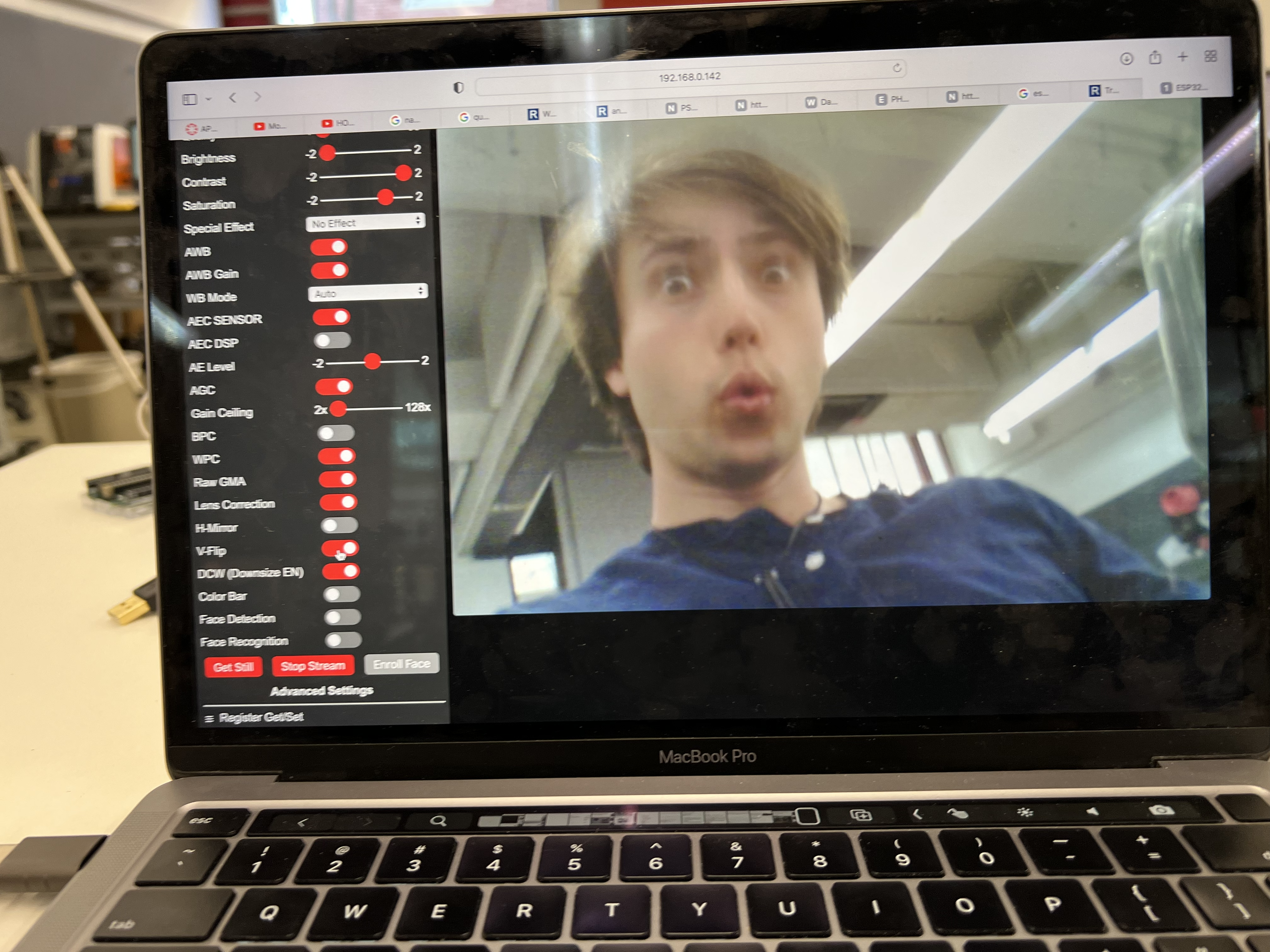
After installing the ESP32-CAM library, I uploaded the example code by opening the Arduino IDE and navigating to Files → Examples → ESP32 → Camera → CameraWebServer. This code is ready to go as long as you change variables ssid and password to the values corresponding to your local network. This example code provides quite a robust interface, and the quality on the ESP32-CAM is surprisingly good.
If we wanted to implement this into our owl, we'd have to either limit the rotation of the head or provide the camera with its own battery source, preventing wires from getting tangled as the owl rotates.